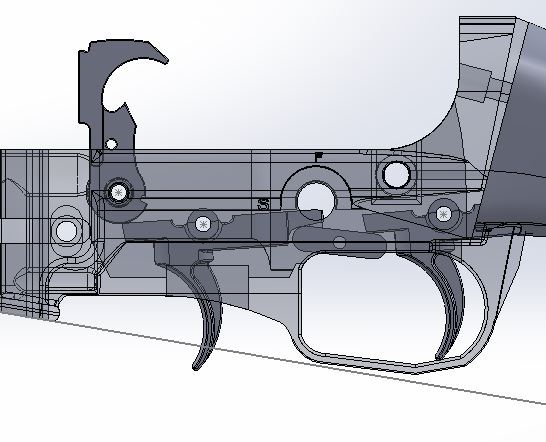
With my lower printed it's time to fit everything. Everything in the CAD file is pretty much drawn to size, which means that in the physical print, everything has slightly too much material. I'd rather have too much than not enough so I'll leave it like that, but it does mean that the lower will require a little fitting. All the holes get cleaned up with appropriate sized dill bits, and any burrs or bumps where other parts fit need to be filed smooth. I left the surfaces where upper sits on the lower slightly too big in the CAD so that I could get a perfect zero slop fit between the upper and lower(particularly in the buffer tower area), and that also means that there should be enough material to make it fit well with any brand of upper. This makes it less plug and play than a standard AR lower, but the end result is a better fitting part. I also slightly redesigned the trigger transfer lever to make it stronger as a printed part. If it were made from metal, the original 1/4" x 1/4" size will still work fine.
With the lower assembled, I could mock up all the rest of the parts I have on hand. I'm using a Bear Creek 16" stainless barrel, with a matching cheap e-bay muzzle brake(which may not do much, I mostly just like how it looks). I'm using a Yankee Hill low profile gas block installed backwards so that the gas port on the barrel is covered(and the YHM was the cheapest one I could find). A standard barrel nut holds the barrel on, and my yet to be designed handguard will clamp around it. It will be a free floating guard, but if it seems like it needs support, I'll tap the tube hole in the gas block for a front mounting screw. The scope is a 3x9 that my Dad had laying around, and the magazine is a 10 round AR Stoner(actually made by ASC, and reported to feed the 7.62x39 reliably). I'm waiting on a set of screw together anti-walk pins for the trigger and transfer bar, and I still have a lot of work to do for the furniture, but it actually kind of looks like a gun now.
Tuesday, December 31, 2019
It is as easy as it looks, mostly.
You know, any time anybody finds out you have a 3D printer, the very first thing they almost always ask is "Have you printed a gun?" Well, now I can actually say yes. I mean, I've printed several TV/movie costume prop guns for friends, but never anything actually usable. And while this isn't a complete firearm, it qualifies as such on an AR based rifle. I got my SCR lower CAD file updated to where I wanted it, threw it in Cura, and hit print. 16 hours later, here's what I had:
I'm using eSun PLA+, and I chose grey for this project. I will probably eventually reprint it in black after it's tested and proven, but for now the grey will show any cracks or wear very well. I recently watched a Youtube series from CNC Kitchen where he did a bunch of tests showing how print settings can affect print strength, and I recommend that everyone who has a printer go through and watch them. Using his videos as a guideline, I'm using .16mm layer heights, 8 walls, 99% infill, .45mm line width, and 75% fan at 220°C/60°C bed. I almost never use a brim, but I chose to here because every now and then a completely solid(or at least 99% solid) part pull off the bed.
It took an hour or so to get the supports off. I'm not satisfied with how it looks. Because of the way I had to place it diagonally on the print bed to fit my printer, there is a lot of banding in it. Overstuffing the line width like I did (.45mm line width extruding from a .4mm nozzle) helps make the print stronger, but also exaggerates the look of the banding. It's not the prettiest, but it should be strong and functional.
I'm using eSun PLA+, and I chose grey for this project. I will probably eventually reprint it in black after it's tested and proven, but for now the grey will show any cracks or wear very well. I recently watched a Youtube series from CNC Kitchen where he did a bunch of tests showing how print settings can affect print strength, and I recommend that everyone who has a printer go through and watch them. Using his videos as a guideline, I'm using .16mm layer heights, 8 walls, 99% infill, .45mm line width, and 75% fan at 220°C/60°C bed. I almost never use a brim, but I chose to here because every now and then a completely solid(or at least 99% solid) part pull off the bed.
It took an hour or so to get the supports off. I'm not satisfied with how it looks. Because of the way I had to place it diagonally on the print bed to fit my printer, there is a lot of banding in it. Overstuffing the line width like I did (.45mm line width extruding from a .4mm nozzle) helps make the print stronger, but also exaggerates the look of the banding. It's not the prettiest, but it should be strong and functional.
Saturday, December 28, 2019
Stuff that matters
This is the part of projects like this that I like the least, modifying parts that I actually paid for. Though I pretend to know what I'm doing, I'm pretty much making it up as I go along and I'm never certain anything is actually going to work. With the printed stuff it doesn't really matter, cut, grind, file, and if I do it wrong I can just reprint it and I'm not really out much except time. But now I'm to the part where if I screw something up I actually have to buy another one(and pay shipping, and wait a week).
I'm using a side charging 7.62x39 upper receiver and BCG unit from Bear Creek. It's inexpensive, and to my untrained eye looks to be decent quality. The problem is that the bolt carrier is too long since I don't have a buffer tube for it to slide into. Fortunately, the tail of an AR bolt carrier doesn't really do much to stabilize the bolt, all the tight clearance sliders where it contacts the upper receiver are on the front section. So out comes the cutoff wheel. A few whacks and some cleanup with a flap wheel, and our bolt carrier is a much more convenient size.
While it was all apart, I did some work on the firing pin too. Google says that 7.62x39 doesn't always fire reliably in AR platforms, especially the harder primer Russian steel cased stuff that I use. One fix is a heavier hammer spring, but that can negatively affect trigger pull. The other fix is to use an "enhanced" firing pin. What's the difference between the standard and enhanced firing pin? The stop shoulder is .010" shorter on the enhanced pin so that the firing pin protrudes just a little but further. If you don't have any size reference, .010" is about three sheets of paper thick. That little bit can make all the difference in the world on X39 ARs. Enhanced firing pins are cheap, but why spend $10 when I don't have to? The left side of the line is what we need to take off:
You don't even need any special tools to do this. You'd think a firing pin would be too hard to file, but they aren't. Just chuck it in a drill and have at it with a file. It's a 5 minute process.
While I had the grinder out, I cut off the trigger bit of the front trigger. It doesn't need to be cut all the way off, just far enough so that it doesn't hit the inside of the receiver.
Once I've verified that everything works and have uploaded my files, if you want make one yourself here's where the tail of the trigger is cut. The angle isn't super critical and I just used some scribed lines to cut it:
At the request of a guy I know, here's what the Bear Creek side charging upper looks like and a few details. The charging handle is .740" from the front of the bolt carrier, and it uses an ordinary 10-32 socket head screw going through the handle it's self. I don't know if Bear Creek actually makes these uppers or not, I've seen what looks like the exact same one unbranded from several retailers. I went with Bear Creek because I was ordering a barrel from them anyway and it saved on shipping.
I'm using a side charging 7.62x39 upper receiver and BCG unit from Bear Creek. It's inexpensive, and to my untrained eye looks to be decent quality. The problem is that the bolt carrier is too long since I don't have a buffer tube for it to slide into. Fortunately, the tail of an AR bolt carrier doesn't really do much to stabilize the bolt, all the tight clearance sliders where it contacts the upper receiver are on the front section. So out comes the cutoff wheel. A few whacks and some cleanup with a flap wheel, and our bolt carrier is a much more convenient size.
While it was all apart, I did some work on the firing pin too. Google says that 7.62x39 doesn't always fire reliably in AR platforms, especially the harder primer Russian steel cased stuff that I use. One fix is a heavier hammer spring, but that can negatively affect trigger pull. The other fix is to use an "enhanced" firing pin. What's the difference between the standard and enhanced firing pin? The stop shoulder is .010" shorter on the enhanced pin so that the firing pin protrudes just a little but further. If you don't have any size reference, .010" is about three sheets of paper thick. That little bit can make all the difference in the world on X39 ARs. Enhanced firing pins are cheap, but why spend $10 when I don't have to? The left side of the line is what we need to take off:
You don't even need any special tools to do this. You'd think a firing pin would be too hard to file, but they aren't. Just chuck it in a drill and have at it with a file. It's a 5 minute process.
While I had the grinder out, I cut off the trigger bit of the front trigger. It doesn't need to be cut all the way off, just far enough so that it doesn't hit the inside of the receiver.
Once I've verified that everything works and have uploaded my files, if you want make one yourself here's where the tail of the trigger is cut. The angle isn't super critical and I just used some scribed lines to cut it:
At the request of a guy I know, here's what the Bear Creek side charging upper looks like and a few details. The charging handle is .740" from the front of the bolt carrier, and it uses an ordinary 10-32 socket head screw going through the handle it's self. I don't know if Bear Creek actually makes these uppers or not, I've seen what looks like the exact same one unbranded from several retailers. I went with Bear Creek because I was ordering a barrel from them anyway and it saved on shipping.
Friday, December 27, 2019
Don't let your dreams be dreams!
It might not look much different, but practicaly everything from the magwell back on my SCR lower has been changed. I lowered and reshaped the trigger guard so that the bottom is at the same level as the magwell for easier printing, I moved all the safety features from the left side to the right, and thickened up some areas for a stronger print. I also changed everything that needed to change for the lever trigger system from my last post.
I printed out the transfer lever and trigger, and to save time and filament I only printed the back half of the lower. I also trimmed the tail of the front trigger as necessary for the transfer lever with my dremel. I put it all together and much to my surprise, it actually works. Even with the printed parts, the trigger pull is short and crisp. It's a little heavy, but not much more than the original(and definitely less than my Uzi). Not pictured but the safety works too and is index finger selectable. It seems to work well enough that I'm going to leave them as printed parts for now. The only extra parts needed beyond the printed bits are a 3rd AR trigger pin, and a 1/8" pin for the transfer lever. I don't really have a good way to capture the rear trigger pin yet though(though for as often as it will likely ever come apart, it could just press fit into the plastic receiver if I don't come up with something better).
Here's how the parts fit together when cocked(minus a little bit of wobble because the pins are just kind of sitting in the tops of the holes):
Here's about how far everything moves when it's fired. The safety acts as an overtravel stop for the mechanism, and the original trigger spring is strong enough to reset everything when you let off the trigger.
I printed out the transfer lever and trigger, and to save time and filament I only printed the back half of the lower. I also trimmed the tail of the front trigger as necessary for the transfer lever with my dremel. I put it all together and much to my surprise, it actually works. Even with the printed parts, the trigger pull is short and crisp. It's a little heavy, but not much more than the original(and definitely less than my Uzi). Not pictured but the safety works too and is index finger selectable. It seems to work well enough that I'm going to leave them as printed parts for now. The only extra parts needed beyond the printed bits are a 3rd AR trigger pin, and a 1/8" pin for the transfer lever. I don't really have a good way to capture the rear trigger pin yet though(though for as often as it will likely ever come apart, it could just press fit into the plastic receiver if I don't come up with something better).
Here's how the parts fit together when cocked(minus a little bit of wobble because the pins are just kind of sitting in the tops of the holes):
Here's about how far everything moves when it's fired. The safety acts as an overtravel stop for the mechanism, and the original trigger spring is strong enough to reset everything when you let off the trigger.
Wednesday, December 25, 2019
I'm just going to lever this right here.
Here's my latest idea for my SCR trigger. Instead of a big long
extended trigger, it uses a short lever to transfer motion from the new
trigger to the tail of the original one. It uses a second AR trigger
with the tail cut off, but it could probably be a printed part(I'll try
it just to see). The lever can be made from a chunk of 1/4" square
stock, although it may be able to be printed too. The original AR
trigger needs some of the tail cut away for the lever but since there is
no disconnector in the way that's not a problem. Here you can see how
everything sits in the cocked position:
In this system, the rear trigger only needs to move 5°-6°, pretty much the same as a standard AR trigger. If I decide it works, I'll add more material around the lever pin so I've got a stronger print. I'm also going to reshape and relocate the trigger guard down a bit too so the lever won't protrude into it(and it will print better with less support if the bottom of the trigger guard is inline with the bottom of the magwell). The original trigger spring should reset everything. Here's how things move when it's fired. It still probably isn't going to be the world's greatest trigger pull, but it might be good enough.
Tuesday, December 24, 2019
Stocking up.
I did some more work on my SCR stock. Not so geometric shapes like this are hard for me to do, it's not really something Solidworks was made for and I'm learning a lot as I go. I actually printed two more stock sections in the past few days. I got the first one off the printer and thought "Geez, this doesn't really feel different than my first attempt." And that's because I printed the same original test file again...oops. So then I printed the right one. It's much better and is a much more comfortable grip and easier/shorter trigger reach. It still needs more work as the base of my thumb sits uncomfortably against where the main section of the stock meets the grip portion. It's hard to show the difference, but here are the two versions together showing how much lower the grip section of the new one is. This one is also printed in Marble filament because I think that's what I want to use for the final stock/handguard prints. I live in WI after all, and winter is a thing we generally do pretty well.
For ease of use, I chose to dovetail the stock onto the receiver. That should give me a nice strong connection while only needing one small bolt to hold it in place. The dovetail also gives me a lot more solid material in the area where the lower is most likely to break in use. If need be, I can add a hole or two in that area to JB Weld in some steel reinforcing rods too. You can see how it slides on here:
Sunday, December 22, 2019
The first of many
I got my first SCR type lower receiver printed. This print was done quick with minimal shell thickness and infill because I'm just checking fit and function, and is in no way shootable. I also printed out the grip chunk of the stock so that I could see how it felt in the hand. Even though I'm never going to attempt to fire this one, for legal reasons(namely the short section of test grip), this is a pistol receiver. After playing with it some, I've come up with a list of things to work on. First, I'm going to flip the safety lever to the other side. It's not thumb reachable on the left side, but is index finger reachable if the lever is on the right. Second, the grip is way too high. I've got average sized hands and while I can reach the trigger, it isn't really comfortable so I'm going to move the grip down and forward some. Speaking of the trigger, it does work, but as expected the pull is very long and creepy. I'll work on making something better for the next one.
Subscribe to:
Posts (Atom)