There's nothing special about a cam sensor. It's just a three wire(5V in, ground, signal) hall effect sensor. It works by sensing the magnetic difference between a raised ridge and a low area on the cam gear. Knowing that, I set out to find a replacement sensor. I figured if I couldn't find one that fit, I would just machine up an adapter.
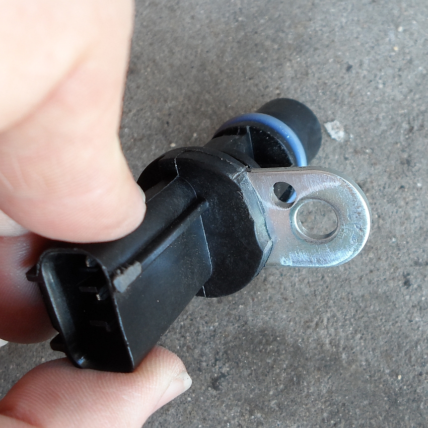
As luck would have it, there is an available sensor that fits the hole in the block. It's the sensor from 2000-2008 Dodge 3.7L, 4.7L, 5.7L, and 6.1L engines used in Rams, Dakotas, Durangos, and Chargers. It also fits a few Chryslers, and a ton of Jeeps. They used this sensor in hundreds of vehicles, and is is readily available through any parts store for around $25. The specific application I gave the counter jockey was a 2006 Dakota 4.7L. It's BWD part# CSS635. This sensor doesn't just fit the hole, it's exactly the same diameter as the original. Even the electrical plug is the same. The only problem with this sensor is that it's meant to attach differently, so the bracket is wrong. Here's my original Viper sensor(grey) next to the new Dakota sensor(black):


Here are the supplies you'll need to get. All are available from any hardware store.
3/4" x 3/4" x 1/8" aluminum angle
10-24 x 1" socket head cap screw
10-24 locknut
#10 x 1/4" spacer
one #10 washer
First, a hole needs to be drilled in the tab. I'm using a 10-24 allen screw and this is just a clearance hole, so the hole gets drilled with a #9 drill(13/64" is close enough if you don't have a number drill set). The location of the hole isn't critical, the bracket we're going to make has a bit of adjustment built into it.


With the sensor modified, all we need is the bracket. I used 3/4" x 3/4" x 1/8" aluminum angle. The bracket is very simple, it's just a drilled hole and a cut slot. There is a little bit of fudging room, so if your dimensions don't exactly match mine, it should still work.


Now, before we go installing this thing, there's a very important step that can't be missed. Since the sensor is depth adjustable, we have to make sure the camshaft is positioned correctly. The pickup ring on the cam gear is basically a ring, half of it down low, half sticking up. If you don't have the cam in the right place and you're in the "low" portion of the gear when you set the sensor depth, the raised portion WILL break the sensor off as soon as you crank it over, and you WILL have to remove the oil pan to get all the pieces out(ask me how I know...).
To check where the cam is, you'll need a small ruler. A standard 6" machinists scale(available at most hardware stores) works great. You need to measure from the face of the block to the cam gear. I'll just steal a picture from my service manual for this one:

There's one last thing we have to do before installing this thing. As I mentioned, the Viper sensor is depth adjustable. Ideally, you want a .030" gap between the sensor and pickup ring. Too close and it could rub, too far and it won't pickup properly. Originally, there was a paper shim glued to the face of the sensor. It set the gap and got peeled off as soon as the engine was started. Since the Dakota sensor isn't supposed to be depth adjustable, it doesn't come with a shim. You can't buy a single shim(because who needs just one?) but a whole box of them is only $5 (Napa PN ECH CSS639, Standard PN PC339 crank and cam spacers are the same part). They're also available on e-bay. Since I have a digital caliper, cardboard, and spray glue, I made my own. Turns out that two layers of cereal box is exactly .030" and 3M 77 spray glue is sticky enough without being too sticky. Don't worry about the shim floating around in the oil pan. Because of the Viper's pickup arrangement and pan baffling, the disk can't get sucked into the oiling system, and should be flushed out at your next oil change.

Now the fun part, actually installing the sensor. It's on the front left side of the block. I had mine in and out so many times I got pretty good at it. After removing the airbox and intake tubes, I found that it was actually easier to get to the sensor from the right(pass) side, reaching in under the oil cooler. Stubby wrenches are a big help. Lubing the o-ring with some oil helps too. The spacer shim will set the depth, you want just light pressure against the cam gear. Once you get the sensor in place, you can get the bracket lined up where it needs to be and tighten the bracket bolt and hold down bolt.

This will fit '96-'06 Gen II/III Vipers. It may also work on Gen Is, but I'm not sure. The Gen I sensor is slightly different, but I'm not sure what's different about it. I think it's just the plug, but I'm not sure. If it is just the plug, this will work on Gen Is too, just splice in the proper pigtail for the new sensor.
The last thing I'll say is that I wasn't kidding about checking the block face to cam gear depth being the most important part. If you get it wrong, you WILL break a sensor...

A minor update: The whole point of making the bracket the way I did was so that a guy could make one for himself in his garage without special tools. Since there are people like me who have access to greater means, I decided to draw up a CNCable bracket. It's still dirt simple and can be machined entirely in one setup, except for the purely cosmetic radiused corner on the bottom left side. It eliminates the need for the spacer, washers, and locknut.

So did you make up a couple hundred of these cnc brackets? Some of us aren't very crestive....
ReplyDeleteVery cool, great job with the information!!
ReplyDeleteHi Jeff, this is a lifesaver. It would even be worth it to buy some of your brackets if you ever decided to sell them!
ReplyDeleteHey could I get the cnc cad file whatever. I'm going to try to get this made.
ReplyDeleteAs it happens, I uploaded the CAD files to Grabcad several years ago. https://grabcad.com/library/gen-ii-gen-iii-dodge-viper-cam-sensor-adapter-bracket-1
Delete