Showing posts with label 1911-ish. Show all posts

Monday, March 1, 2021

La Llama XV esta completa

I'm done with my little Llama XV 22lr.  After test firing, I cleaned the frame and painted it.  I tried something new with the paint, and I'm not really happy with how it turned out, but it will do for now.  I tried to replicate the nickel plating on the metal as best I could.  I use Rustolium Chrome spray paint and topped it with a matte clear.  It looks ok, but it didn't seem to stick to the print well and it chips super easy.  Next time I'll try a base coat of SEM Color Coat under the top coats because that stuff sticks to prints great.  The entire frame as well as the grip panels are 3D printed and here's how it turned out.  It's easy to forget just how small the Llama XV is when you see it alone in pics, so I included my partially printed full size 1911-ish in some of the pics for scale.


Saturday, December 7, 2019

That's that.

The Gun Kote Flat Black actually turned out to be pretty close to whatever finish Rock Island uses on their slides.  I decided that the machining on the grips looked to good to cover, so I left them bare aluminum.  I'm not super pleased with the finish on the frame though, so I will likely repaint it.  It will do for now.  As I said last time, all that's left is to put the slide on.  It goes on like any other 1911 slide.  The only other thing I did was put in an EGW shock buffer on the recoil guide to keep the steel slide from smacking the aluminum frame.

Who likes beauty shots?


Friday, December 6, 2019

Closer

Getting close to the end now.  My 1911-ish gun gets assembled like a 1911...ish.  It's mostly like a 1911, but not quite.  I mentioned that because of the integrated mainspring housing this thing is a bit fiddly to put together and has to be done in the right order, and here's how to do it.

Start by dropping in the trigger.  Then the sear spring gets slid down into it's recess until the tab on the spring clicks into the slot in the magwell.  To help keep it in place, a roll pin goes through the grip right behind the sear spring.  The pin doesn't need to be a tight fit, the grips will hold it in place.  The mag release can go in now too.

The next bit can be tricky the first time you do it.  We have to install the mainspring into the housing.  I use a screwdriver and the edge of the table to compress the spring.  Gotta be careful not to slip and stab yourself.
Once the spring is compressed far enough, drop in the mainspring retainer pin through the hole in the MSH.  It goes from the outside in, just the opposite of a standard 1911.  It's only there as an assembly aid and will be removed later.
Next up is to put the frame on the grip section.  Install the sear and disconnector in the frame, then slide it together.  I use a hook to pull the sear spring back out of the way so that it can be put on the correct side of the sear.

Next up are the grips and the pin in front of the trigger guard.  They should be a tight fit because you don't want any play between the frame and grip section.
Next is the hardest bit, installing the hammer.  You've got to compress the mainspring enough to get the hammer lined up so you can drop in the pin.  I've found that the easiest way is to make sure the hammer strut is lined up in the mainspring cap, then press hammer against the edge of the table with enough force to get the pin in.  Get the angle just right, and it's not too bad.  Once the hammer is in, you can pull out the mainspring retainer pin because it's not doing anything anymore.
Next is the grip safety.  My printed GS slides straight into the back of the frame, then cock the hammer and install the safety lever like a standard 1911.
That's pretty much it, the frame is completely assembled.  Check everything for proper operation, and then install the slide like you would in any other 1911.  I'll add too that I'm using an EGW shock buffer on my recoil guide, just to keep the steel slide from smacking the aluminum frame.


The finish is in sight!

I'm not really a big fan of the two tone frame/slide look on 1911s, so I had to do something with my bare aluminum receiver.  As luck would have it, I have a little bit of KG Gun Kote Flat Black left over from my Uzi.  It's not a perfect match to the Rock Island slide, but it's close enough for now.  Someday I might completely refinish both in the same color, but that day is not today.  I really like Gun Kote.  It's durable and it's just so easy to use.  Prep your part, spray it on, and bake.  It leaves a thin, hard, and fairly durable finish too so I sprayed the whole receiver, rails and all(300 rounds so far in my Uzi shows no wear at all on the Gun Kote where the bolt slides against the inside of the receiver).  Here's my frame, fresh out of the oven.


Getting a grip, safely

In order to save an entire $30, I decided that I wanted to 3D print the grip safety on my 1911-ish.  I figured that if nothing else, it's already a back up to the main safety so if it didn't work the gun would still be safe to use.  I had a surprising amount of trouble with it, and it took several tries to get it right.  Because of my integral mainspring housing, an off the shelf .250 radius 1911 GS would still work, but will need the little feet trimmed off the bottom in addition to all the standard fitting that you'd need to do so that the GS can be put on after the upper and lower parts are assembled.  Here are all my attempts next to the steel part that came with my parts kit.  Each one is just a little different than the previous version:

Friday, November 29, 2019

Oh yeah, it's all coming together.

Everything is fitted to the 1911-ish, so it's time to put it all together.  Because the mainspring housing is integral with the printed grip section, assembly is a bit fiddly.  It's not quire as straight forward as a standard 1911, but it's not too bad and it's not like it will have to come completely apart often.  I'll make a "how to assemble" post at some point.  I still need to reprint the grip safety in black too, I'll do that when I paint the frame.  Anyway, here's how it looks all together:


All that's left is to test it.  I got out my trusty "test stand", rope, and big tree to hide behind. 


Wednesday, November 27, 2019

Tube stakes

The last part that needs to be added to the 1911-ish frame is the plunger tube.  It's pretty simple, you put it in, then mushroom over the posts inside the magwell.  Before that can happen though, there needs to be someplace for the posts to mushroom into.  To do that, I took my dremel, and cutting carefully with the bit extending through the post holes, added a countersink to the back side.
They sell a tool to stake the posts over with, and it works very well.  I don't have that tool.  What I do have is a lot of random stuff laying around.  This little vice, for example, that I think I made in high school.  I took a setscrew and added a point to it to mushroom the posts.  I just hot glued the pointed setscrew onto the vice since it's a one time use tool. 
I used some green Loctite retaining compound on the posts, then staked them over.  The most important thing here is to find a perfectly sized drill bit to put into the plunger tube so that it won't collapse when you squeeze it.  Is this the worlds greatest tool?  No.  Did it get the job done?  Yes.


1911 feed ramp sanding jig

Here's a more detailed explanation of my 1911 feed ramp sanding jig.  It should work for all full size 45acp 1911s.  To use the jig, slide some 1/4" rod through the magwell so that it rests against the mainspring housing edge of the magwell, with the narrowest part of the jig on the feed ramp. Wrap the jig in sandpaper and sand away. Look at the cutaway pictures to make sure that you have the orientation right while sanding. Make sure that you DO NOT radius the top corner of the ramp, it must be a sharp corner for proper feeding. I shouldn't have to say this but DO NOT REMOVE ANY METAL FROM YOUR GUN UNLESS YOU KNOW WHAT YOU ARE DOING. Metal is easy to remove and hard to put back on. Oversanding the ramp can cause your gun to jam and become unreliable, and it will need to be repaired by a professional gunsmith.  Here's a link to the 3D printed bit: https://www.thingiverse.com/thing:4006165


Ramped up

This is one of those small but very important 1911 detail things, the feed ramp.  I chose to leave it completely uncut and in retrospect I should have just machined it along with everything else.  But there is a library's worth of discussion and argument on what the "best" feed ramp angle should be and I wasn't sure how the barrel would fit so I put it off until later.  And now it's later.  After a whole lot of reading, I decided that despite all the discussion and arguments, it is not, in fact, rocket science.  There are millions of these things out there from hundreds of companies, spanning over a century of manufacturing, and they can't all be the same.  I chose the most commonly recommended ramp, at 31.5°.  I started by laying out some guidelines where the limits of the ramp should be, the most important one is that it needs to be .030" from the throat of the barrel.
Not trusting myself to do an ultra precise angled setup on my little mill, I elected to do all the metal removal by hand.  I can already feel the gun community shudder as I start attacking this with my Dremel.
I may look stupid, but I'm not dumb, and I'm not doing all of it with the Dremel.  I'm just doing the roughest of roughing.  The rest of it will be done with sandpaper.  But how do you make a very precise angle with sandpaper?  With a happy coincidence and a stupidly simple tool.  You see, if you put a 1/4" rod through the magwell so that the back of it rests on the MSH side and the front lays on the feed ramp, it ends up being exactly 31.5­°.  If you then have a 7/16" diameter circle tangent to where it contacts the ramp, you have the exact diameter you need for the feed ramp.  I checked everything in Solidworks, and it all works out perfectly.  I made my tool with some 1/4" rod, and a 3D printed sleeve.  I put a center line on it so I could be sure it stays straight up and down while being used.
Wrap the sleeve in sandpaper, hold the frame in something secure, and have at it. I taped off as much as I could to keep from getting everything scuffed up.
I sanded using progressively fine sandpaper up to 400 grit, and stopped when I hit the barrel setback line I had scribed.
Then I hit it with some Mother's Mag and Aluminum polish to shiny it up.
I don't know how accurate it actually is, but it feeds very well with my dummy rounds.  We'll have to wait to see how it works with actual bullets.


Sliding on in.

Next up on my 1911-ish project is fitting the slide.  I machined the rails just a tiny bit oversized to leave room for hand fitting so that I could get the best possible fit between my frame and slide.  When I went to start fitting it though, I noticed something odd.  My frame rails were bent.  You can see the slight wave in the left rail here:
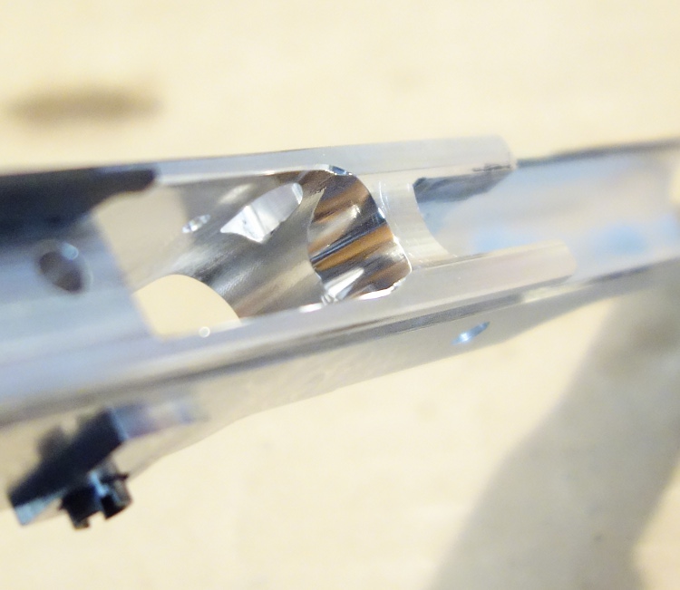
Weird, right?  Here's what I think happened.  When I clamped the frame in the vice for the last CNC op, the rails were facing down.  I can see witness marks from the vice showing where it was.  Here's where I had it clamped in the vice: 
I didn't think anything of it because there was solid aluminum in front of and behind the magwell and the vice wasn't actually touching the rails, so I really cranked down on it.  All I can figure is that the vice compressed the aluminum, but because there was no support at the magwell those areas just bent instead of squishing.  I'm not super concerned because it shouldn't really affect strength and some frames omit that portion of the rail entirely.

Anyway, fitting a slide is easy, but tedious.  File, check, file, check, repeat until it fits.  Instead of Dykem or some other layout fluid to see where the frame is making contact, I just use a black Sharpie.  Any spots that end up shiny get material removed.  You'll want to go slow and check frequently because it's easy to overcut and hard to fix if you do.  It probably only took me an hour or so to get my slide fitted and functioning right.  To my surprise the barrel needed virtually no fitting at all, just adding a very slight chamfer to the VIS area of the frame(which I'd purposely left out when I machined it).


Saturday, November 2, 2019

Weld. JB Weld.

A lot has happened since my last update on this project.  I got all the parts fitted into my printed grip section, and then decided it didn't fit quite how I wanted.  Instead of more filing and fitting, I just changed the CAD file and reprinted it.  There are still some print artifacts in the latest one so I'm still not 100% happy with it, but it will do for now.

The next big holdup was the grip bushings.  The grip bushings on this particular gun are very important because they help in locating and locking the upper receiver and grip section together with the aluminum grip panels.  The grip bushings that came with my parts kit were cheap.  Very cheap.  The first time I screwed one into my freshly tapped frame I thought I stripped the threads out of the frame, but I tried a second one and it screwed in fine.  The first bushing was out of spec.  Given the importance of the bushings on this build, I decided I needed higher quality ones.  I bought THESE US made grip bushings and screws from e-bay seller "wvag".  They are really nicely made, and definitely worth the $7 that they cost.

Even with the nice bushings, I was concerned that the bushings would pull out of the plastic under recoil.  To lock the bushings into the plastic grip section, I chose JB Weld.  PLA+ filament doesn't get along well a lot of adhesives, but to my surprise JB Weld sticks to it very well.  So that's what I used to lock in the grip bushings, and fill in the gap between the bushing and the pocket to help support them for any side loads that they might see.

With the bushings locked in place, I felt comfortable putting the mainspring in and putting it all together.  Assembly is a bit fiddly because of the fixed mainspring housing, and I'll go through the assembly process in a future post.  There's still a lot of fitting and tweaking left to do, but so far it works pretty much how it's supposed to.


Saturday, August 3, 2019

Just getting a grip on things

A seemingly minor, but very important part of my 1911-ish project are the grips.  It's the grips that will hold the 3D printed lower onto the machined upper frame.  As such, they needed to be made out of something more substantial than plastic, so I made them out of aluminum.  I had trouble deciding on what kind of pattern I wanted, so I decided to stick with the classic double diamond.  Tedious to draw on my old slow machine, but it turned out well.  I spaced the checkering far enough apart so that most of it could be reached with a 1/16" ball mill, then basically did a constant stepover across the whole thing with the cutter stepping over .005" at a time.

Unlike regular 1911 grips which are just sort of there, these ones are machined to as tight a tolerance as I can reasonably hold so that they locate accurately and repeatable on the grip screw bushings.  All the critical tolerance features were machined in one setup on the back side, so to machine the top side instead of using a fancy jig or fixture, I stole an idea from work and bolted them to a subplate.  I have a plate with 1/4" holes spaced every 1/2" so that for the 2nd side operations, I can simply bolt the block of aluminum down with 1/4" bolts.  I added some tabs to my CAD file for the bolt hole bosses to attach to.  Here's how it looked fresh off the machine:
The leftover tabs are only .050" thick, and it was quick work to trim them off and file the edges flat:
Here's a closeup of the checkering. The diamonds are spaced .100" peak to peak, and each diamond has a .019"x.040" flat at the top so that it's textured without feeling sharp.
Here's how it looks in Solidworks.  Everything is spaced as far apart as it is because I planned from the get go to cut it with a 1/16" ball end mill, and there are no fillets drawn at the bottom of the checker diamonds though I knew they would end up filleted anyway because of the cutter radius.  The gap between the diamonds is just enough so that the tip of the ball mill hits the bottom surface.  The finish machined part doesn't exactly match the CAD drawing because of that, but with my old slow computer it was easier to let the cutter do the work instead of trying to draw exactly what I wanted.