Sunday, June 28, 2020

How to put a used AR-15 sight on a new barrel

As the title says, today I'm putting a used AR-15 front sight on a new barrel for my M16A1 project.  I'm going to try to make this an actual how-to so I hope it all makes sense.  Like many other guns, M16/AR-15 front sight towers are pinned to the barrels.  The difference here is that they use tapered pins instead of straight ones.  If everything is new and undrilled, it's not so big a deal.  But this one is used and it's not something the average AR DIYer has the tools to do because the sight has the holes already, but the barrel doesn't, so just center punching and drilling isn't going to work, and the tapered pin holes make things worse.  At a minimum you need a drill press, but preferably a mill should be used.  The "easy" solution is to use something like Brownell's Retro barrel that already has the sight pinned onto it.  I, of course, always do things the hard way because as I've previously discussed, I'm stupid.  I also want to use as many of my original M16A1 parts as possible.  The barrel I'm using is a JSE 20" "lightweight" profile nitrided barrel with a 1x9 twist and a .625" gas journal for the early Colt gas block/front sight.  It's a pretty good match for the M16A1's original "pencil" profile.

The hardest part of this whole process, at least for me, was trying to figure out how to make sure the sight block was lined up with the upper receiver.  If you don't get the alignment just right and it ends up canted you may not be able to get it sighted in.  I ended up using one of my precision parallels in the rear sight channel of the upper for the back, and used the front sight ears for the front.  This isn't the best way to do this, but it's the best I could come up with without making a whole dedicated jig.  Once everything is aligned, a vice grip on the front of the gas block is enough to keep it in place as long as you don't knock it around too much.  If you're not using smooth jawed vice grips like mine, put some padding under it so that you don't mar up the finish.  Also be sure to install your barrel nut and handguard retainers before you start because you won't get another chance and your spacing will be wrong without them.  Make sure your front handguard retainer is tight against the stop or it will rattle.
*Addendum: It has been brought to my attention that I could have just boresighted it to get things lined up, and now I feel stupid(especially considering that's how I roughed in the sights after I got everything assembled).

The second hardest part of this whole thing is getting it all square in the mill so that our holes get drilled straight.  This requires a little bit of faith in Colt.  If your sight block doesn't have a sling swivel, you can use the swivel pin hole for alignment.  But if it does have the swivel riveted in like mine does, you'll have to use the gas tube pin hole.  This is where the faith come in.  I am trusting that Colt drilled all the holes in this thing parallel to each other.  As a machinist by trade, I have calibrated eyeballs so to get everything square I used a drill bit in the gas tube pin hole as an indicator and eyeballed it so that it was parallel to my mill's spindle in both X and Y.
Next up was using the centerfinder shown above to find the center of the rear pin hole.  Once found, it was time to drill.  As I mentioned in the beginning, this is a nitrided barrel which means that it's just going to laugh at regular drill bits.  Carbide drills are available, but because we're essentially drilling half a hole the bit will want to wander so they're not a great choice either.  The best choice is a carbide flat end mill.  It will cut the best without wandering.  I'm using a 1/8" end mill, which is only .005" bigger than the proper #31 drill.  This will be ok because the pins are tapered and the idea is to cut down through the barrel but stop before the end mill gets all the way through the sight block.  I don't have any pics of this, but it's just drilling a hole, nothing exciting.

After the hole is drilled, it needs to be reamed.  It needs a #2/0 tapered reamer.  As much as I hate buying single purpose tools, sometimes you just have to have the right tool for the job.  I bought one on e-bay for $8.  I was very nervous using it because it's pretty small and I didn't want to break it.
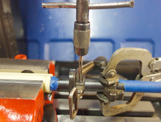
Go slow, use lots of cutting oil, clear the chips often, and check your progress frequently.  It's very easy to go too far.  Using a tap handle by hand, I went 5 turns of the handle between checkings because once it starts cutting, it cuts fast.  Making sure the hole is free of chips, you want the pin to be sticking up just shy of 3/16" when you drop it in with no pressure.
Once you get it that far you can take the assembly out of the vice and drive the pin home.  It's best to have a proper block for this, though a block of wood will work in a pinch.  I found a punch block on Thingiverse and printed it out.   If you reamed your holes right the pin should be tight when it's sticking out an even amount of both sides of the sight block.
With the rear pin in, we can leave the vice grips off and do it all again for the front pin.  Follow all the same steps as the first pin.  If you've never used this kind of centerfinder, they're very handy.  The pointy bit goes in the hole you want to locate, then you just move your X and Y around until the pointy bit is lined up with the shank.  You set it by feel, so no calibrated eyeballs required.
Once all the fun and games are done, you should have your vintage used sight properly installed on your brand new barrel. 
To be honest, this took me the better part of a day.  Lots of checking, double checking, triple checking, and checking again.  It's not particularly hard, but if you don't use jigs you really have to take your time.  *Future post spoiler alert*  So how did I do at lining things up?  Pretty good.  I had to set the rear sight about 1/3 to the right in order to get it sighted in so I didn't get it perfect, but it's more than close enough.


Saturday, June 20, 2020

I always wanted to be a dentist

Gonna be lots of pics in this post.  The worst part of my M16A1 kit by far is the handguards.  For "military hardware," they are very fragile.  They crack and teeth break off fairly easily.  Even "good" parts kits usually have missing teeth.  Mine were very rough.  There were missing teeth, were cracked, had poorly done epoxy repairs, and several coats of paint.


At first glance, I thought they might be unsalvageable.  Uncracked originals are available, but are much more than I want to pay.  Reproductions are available cheaper, but the texture isn't right on them and they don't have the pressed fiberglass look of the originals.  Also, I'm stubborn, so I'm going to play dentist and fix these broken handguard teeth.

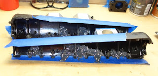
With some patience and a good small pliers, the heat shield rivets can be pulled out.  They are slightly threaded, and twist out like a very course screw.  After a very good scrubbing with Dawn to get decades of oil and grime off the fiberglass, I started by removing the several layers of paint with Citristrip.  Then on to my repair compound of choice, JB Weld.  I stared by grinding out the back side of all the cracks with my Dremel, then using some tape as a dam, gooped on some JB Weld where the missing teeth should have been.
Once it cured, I could sand and file the teeth to shape.  I used the existing teeth from one side as a guide for the other.
Then I moved onto the outside.  First I ground down all the cracks, being careful not to grind all the way through the fiberglass.  The grinder also leave a nice rough surface for JB Weld to stick to.
I really didn't want to paint these, so I tried mixing the JB Weld with carbon black and black paint like I did with the buttpad to darken it up, and smeared it on.
I didn't add enough coloring to the JB Weld.  It looked good when fresh, but as soon as I hit it with sandpaper, it turned a much lighter grey.  Using my sanding blocks, I started with 80 grit sandpaper, then 320, then 600(because those are the grits I had).  The 320 and 600 I used wet.  Not only does the sandpaper last longer and not clog up during wetsanding, it keeps fiberglass dust out of the air(which is itchy as heck if you get it on your skin or clothes).  By sanding with a block, I got a nice flat surface.
While I was at it, I cleaned all the paint off the heat shields, straightened the aluminum as best as I could, hit them with some scotch-brite and reinstalled the rivets I pulled out at the beginning.


I was not satisfied with the color of the JB Weld.  At all.  And I didn't want to paint the whole thing, so I totally cheated.  I painted the JB Weld spots, let the paint dry a few minutes, then wiped it off with a dry rag.  The result was exactly what I was hoping, it turned the JB Weld black without affecting the surrounding finish.
All in all, they turned out better than I expected.  I started with junk, and ended up with usable parts.  It's obvious that they have been repaired, but it fits the style of the rifle.  For a real restoration, a little more sanding and some paint and the repairs would be invisible.

Friday, June 19, 2020

More lego pieces

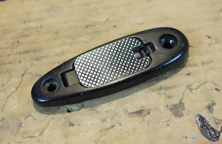
The stock and buffer assembly that came with my M16A1 parts kit are in pretty good shape.  However most, if not nearly all of these M16A1 parts kits come with a cracked buttpad, and mine was no exception.  This thing has had a hard life and was pretty beat up, and looks like it has been set down in the gravel A LOT.  I could, of course, track down an original uncracked one, but this rifle isn't that kind of project.  Here's the biggest crack on the thing, completely split through it.
To fix it I turned to my good friend JB Weld.  As you know, JB Weld is grey, and this piece is black, and that's a problem because I don't want to paint it.  What I did was mix JB Weld with come carbon black(which thickened it up) and some black enamel paint(which thinned it back out).  I couldn't get it to go completely black, but did get a very dark grey.  After a through cleaning/degreasing(Dawn dish soap works great for that BTW), I smooshed it in as best as I could, and clamped it in the vice to cure.  Once it was cured, I wetsanded it first with 320, then 600 grit sandpaper.  I didn't sand out all the imperfections, but did get many of them and it looks nicer than it did, though still used.  The trapdoor is pretty much how I got it and it's got a lot of wear.
With that done I could assemble the lower.  It goes together like pretty much any other AR so I won't bore you with the details.  I will say though that when installing the front takedown pin detent and spring, I recommend putting everything in a gallon size Ziplock and assembling in there so when the detent goes flying, it stays captured in the bag.

Monday, June 8, 2020

Fake it 'till you make it

Fake it 'till you make it, words to live by.  I did some more work on my not-actually-an-M16A1 project.  With my lower machined, it was time to do something about the bare aluminum.  Since this is a "low budget" project, I didn't want to have it anodized.  Budget aside, matching the color of the original upper would be nearly impossible.  Even the real things often didn't match.  For what I'm doing, I also don't need the long term durability of anodizing.

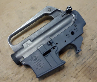
Googling around, people reported that Rust-Oleum Dark Grey primer is a close match to the original Colt XM Grey, so that's what I decided to use.  So, how close is it?  Pretty darn close.  Here's my freshly painted lower next to the least worn area of my original A1 upper for a color comparison:
It actually turned out great and the Rust-Oleum color is a very good match.  I cheated a little bit because of what I had planned though.  I mixed the primer with clear KG Gunkote, giving me what amounted to a tinted clear with the durability of Gunkote.  If you just want the color, this step isn't necessary because the primer will do fine on it's own, but I have more planned for it.  While the color was perfect, there was one glaring problem with it, which you can see here:
The lower looks brand new, because it is.  The color is right, but the fresh painted lower does not match the heavily worn finish of the original upper.  This is where the "fake it" part comes in.  I'm going to artificially weather the finish to try to match the original.  This is why I mixed the grey primer with clear KG Gunkote, it gives me more film thickness without the color being too dense.  The way the original anodizing is done, it looks semi-transparent when it's worn thin and the primer alone won't do that(I mean, primer is made to actually cover surfaces after all and it does that great).

The idea here is to wear through the paint in the areas where it would have been rubbed a lot.  Ultrafine sandpaper is too harsh and not flexible enough, and even scotch-brite is a little bit too abrasive.  I settled on a Mr. Clean Magic Eraser.  Magic Erasers are about the same as 5,000 grit sandpaper.  It cuts through the paint very slowly so I could thin it down without going too far.  It's not a perfect match and it still lacks the scratches from use that the upper has, but for my first project using this technique I think it turned out alright.


Sunday, June 7, 2020

Better Czech yourself, a 3D printed Vz. 61 Skorpion

I don't know why, but I've wanted a Czech Vz. 61 Skorpion pistol since I first learned about them.  It's a simple blowback action but the way this thing operates is like the Rube Goldberg of pistols with so many interlocking pieces to make the thing work, and I love it.  They are available off the shelf, but they cost more than I cared to spend, and where's the fun in that?  Parts kits with torched receivers are available too, but from what people have said it's a tricky reweld and needs a jig.  Also available, and right up my alley, is the file for a 3D printed receiver.  It uses the little .32 APC cartridge(7.65 Browning for you metric folks), so printing should be more than adequate.

I ordered a parts kit from Recon Ordnance, and the customer service is top notch, I'd recommend them to anyone.  The parts in the kit were brand new.  Not lightly used, not tested and put in storage, new.  It didn't look like the bolt had ever even been cocked, much less fired.  Also, to my surprise, all the parts were already semi-auto parts, I didn't even need to convert them over.  The holster included with the kit was used, but that's no big deal.  It was a bit dirty too, so I washed it with Lexol leather cleaner, and gave it a good coat of Lexol leather conditioner.  As received on the top, after cleaning on the bottom.  It had some writing on it that wasn't legible until I cleaned it.  Mr. Burianek from 1Ć, I have your holster lol.
With a few different receiver files available, I decided on the FreeMen version.  I made some changes to the base file to suit my needs.  It's made to use a pistol brace, which I don't want, so I blocked off and shortened the rear where the brace would attach. 
Basically, the whole rear of the receiver is now solid plastic.  I also had some trouble with the parts not fitting as well as I thought they should.  The mag didn't click in as well as it should, so I moved the mag well forward in relation to the mag catch by .020" and now it slides into place easy and locks in solid.  I moved the whole fire control group back .015" because the bolt catch was binding on the lever coming off the FCG.  The hammer didn't cock as smoothly as I thought it should either so initial charging was a pain with just the two buttons on the sides of the upper.  The hammer looked like it was hitting too far forwards on the sear causing a minor bind, and after much testing I ended up moving the hammer pivot hole back .020" in relation to the trigger, now it charges like butter.  It seemed like the receiver was just a little too short front to back, so I moved the takedown pin forwards .035" and now it seems to fit like a glove.  I wanted to use the original pistol grip, but didn't want to shell out the money for the uncommon M15x1 tap needed to cut threads for this single use, so I added them into the file and they are now printed right in. The "fire" detent for the safety didn't line up where it was supposed to either so the notch on top of the lever was hitting the upper receiver, so I moved the detent pocket down by about 1/8".  There are several other little changes too, but nothing major. I printed it in eSun PLA+, 8 walls, 99% infill, .45mm line width(with a .4 nozzle), .16mm layer height, 220°nozzle/60° bed, and only 70% cooling fan.  These settings have proven to give me fantastic layer adhesion and make very strong parts.  On the parts I've destructively tested with these settings, they break like molded plastic does, I get virtually no layer separation.  Here's the finished product:
I tested it with both PPU and the hotter Geko ammo, and it ran flawlessly(which is great because .32 APC is expensive and both these brands are cheap-ish).  I will say though that it's best to wear a hat when out shooting.  It ejects straight up out the top, and having hot casings raining down on you is...interesting...  I think there is still some room for improvement in the receiver, but I'll wait until it breaks or wears out, and then adjust accordingly.  I plan to reweld the original receiver eventually at some point too, but with this printed receiver up and running and many more irons in the fire at the moment, probably not any time soon.

Sunday, May 31, 2020

Check twice, cut once

For the lower receiver on my M16A1 build I'm using a Cerro forged 80% from Right To Bear.  I got it on sale as a "blem" for $30, and for the life of me, I can't find anything wrong with it that would make it a blem.  I'm not going to reprofile it into a "correct" A1 style lower(maybe a future project), but since the rest of this is all Colt M16A1, I decided to engrave the side of my lower to match.  Colt used several styles of markings on their lowers through the years.  With none being more "correct" than others, I decided to just make what I liked based on what I'd seen.  I couldn't find a good CAD drawing of the Colt horse logo that they used, so I ended up drawing my own from scratch.  I got it all drawn up and programmed, and headed to the mill...and that's when the trouble started.

This engraving is the whole reason I upgraded to ball screws on my CNC.  I actually started this project back in January, and only now with the mill done was able to get back to it.  I almost always run my programs on a test piece first, and it's a good thing I did because it didn't work...at all.  I started with a chunk of blue foam, and you can see the results on this test piece here(painted silver for more contrast).
It's a darn good thing I ran a test piece first, or I would have effed up my lower because both the lettering and the logo were very messed up.  The first two attempts were just...wrong...and I couldn't figure out why.  The CAD file was fine, the programming was fine, the toolpath preview on Mach3 was fine, but it wasn't machining correctly. The only think I could figure was that the stepper motors were skipping steps.  I upgraded to ball screws thinking that the more coarse screw pitch would need fewer steps, so it would be less likely to skip.  I was wrong on that too, it wasn't any better with the new screws(although still definitely worth the upgrade for many other reasons).  After much head scratching and internet searching, it turns out all I had to do was increase the pulse width going from my PC to the stepper driver.  My CNC PC is pretty old, and borderline fast enough to run my mill.  It just couldn't output a clean pulse with Mach3's default pulse width, causing the motors to miss steps.  Increasing the pulse width allowed the stepper driver to read the signals better.  Think of it like the difference between yelling "Ah!" and "Ahhhhhh!"  Same message but your brain can process the second one better because it's longer.

With the mill upgraded and test pieces finally looking good, I could do the real thing.  I had to get a little creative to hold it in my vice.  I have a solid block of iron where the trigger would be so that the lower is firmly held in place without the vice touching the thin areas of the mag well and trigger guard.  It's hard to see here, but the engraving turned out perfect.  I left off the Colt manufacturer info block by the selector since this isn't, in fact, a Colt made part and I'm not really trying to fool anyone who takes a close look.  After engraving and while on it's side and all indicated in, I CNC drilled the FCG holes too.

The fire control pocket was next.  I had to get creative with the clamping again, because these things are a weird shape.  As much as I like "hit go and let it run" machining, I had to babysit this thing the whole time.  My coolant mist system doesn't have the air pressure needed to blow the chips out of a deep pocket like this, so I had to pause it and clear the chips out frequently.

It took a while, but that's a pretty nice looking pocket if I do say so myself.  I also left a bridge of material between the the new FCG pocket and existing takedown pin pocket, so even if I hadn't crushed my autosear in a vice, it wouldn't physically fit into the lower.  It's not really necessary and most ARs have this whole area open, but when building a former machine gun with a lower receiver marked like a machine gun, I want my intent to be very clear.


New project time: a retro M16A1 build

Black rifles are like belly buttons, everybody's got one.  It seems like practically everyone has an AR-15 of some sort, everyone but me anyway(unless you count my 715T, which is just a 22LR 702 Plinkster in an AR shaped plastic shell).  So, I decided I should join the club.  Most ARs are lego builds, just buy the parts and slap it together, and this one won't be much different.  The big difference here is that instead of buying new parts I'm starting with a genuine Vietnam era Colt M16A1 parts kit.

My goal for this one is the "battlefield pickup" look.  These are Colt parts, and they're only original once, so I'm going to leave it looking well used.  I got my black rifle parts kit from Royal Tiger Imports on Black Friday when they were on sale.  The packaging from RTI was just plain awful.  All the parts were just thrown in the box with a single piece of bubble wrap around the buttstock.  The gas tube wore a hole in the corner of the box and the bag with all the little bits was broken open.  Consequently, a lot of the pins and little bits rattled out of the box, so I'll have to rob them from a lower parts kit I bought for another project.  After cleaning all the gunk off the parts, here's what I ended up with:

This is a Grade B kit and all in all, not too terribly rough for what it cost.  The forging codes on the upper indicate that it was made some time between '74-'82.  The parts are very well worn on the outside, but the internals look great, like the gun was carried a whole lot but seldom fired. The handguards are very rough with many cracks and missing teeth, but that's not uncommon with these early style handguards and this was a Grade B kit.  I plan to try to fix them, so we'll see how it goes.

I'm going to build it on a standard AR-15 80% lower, and I have to make it a semi-auto only rifle.  The parts kit was a machine gun, and it included all the naughty bits.  You could just throw them away and buy a standard lower parts kit, but I'm cheap, and I like the idea of using as many Colt parts as possible.  Before I even started machining the lower I had to take care of them.  Most of the naughty bits can be converted to semi-only, but one part can't be used at all.  The very first thing I did was crush the auto sear to pieces in my vice, making it completely unusable.
Next up was the hammer.  The M16 hammer has a tail on it that needs to be ground off, making it practically identical to a standard AR hammer.  Original on the left, modified on the right.
Next was the disconnector.  Like the hammer, it's got a tail on it that needs to be removed.  A few seconds with a grinder fixes it right up.
The selector lever is up next.  It's got a fin sticking up in the middle of it that needs to be ground down.  Modified in this way the selector still spins all the way around but the positions give you safe-semi-semi.
Last, the trigger needs some welding.  The AR trigger has a closed back, the M16 has an open back because of the tail on the FA selector.  The end of the trigger needs to be welded closed so that a FA disconnector will not fit.
Just changing the selector or disconnector would make it work as a semi-only rifle, but for legal reasons you need to modify all the parts so that there is no question about your intent.