Sunday, December 13, 2020

Llama XV progress

I'm now on V3 of my baby Llama frame.  Every iteration of this thing gets several changes and at this point my Solidworks feature tree is just a mess.  With V3, everything fits and the action hand cycles and resets like it should.  The problem now is that the safeties don't work.  It wouldn't be that big a deal, but the way it is now the thumb safety can slide up into the notch on the slide, locking the slide closed while still being able to fire.  If this happened, I think the force of the slide would blow the safeties off the back of the frame, and my hand would have a really bad day.  So back to the virtual drawing board to try to get the safeties to work.  Here's how it looks so far with everything assembled, standard 1911 magazine included for size reference:


Sunday, December 6, 2020

Baby on board! A Llama XV miniture 1911 clone

I saw one of these at a gun show years ago, and didn't buy it because the guy wanted $450 for it, but I always thought it was really neat.  They haven't gone down in price since then either.  Then I found a frameless parts kit on Every Gun Part, and when they had their Cyber Monday 50% off  sale I didn't hesitate, and picked it up for $100.

It's a Llama XV, a Spanish copy of the 1911 in 22LR, but unlike most 1911-22's that are still full size, this one is scaled down considerably.  It's not just shorter like a Commander or Officer frame gun, the whole thing is uniformly scaled down in all directions.  All the internal frame parts look exactly like 1911 parts, but smaller.  Since it's a 22LR blowback pistol, the plan is to 3D print the frame for it.  Since it's a fixed barrel most of the recoil stress will be on the slide stop pin and barrel seat area and I think a printed part will be strong enough to handle it.  I took the CAD files I already have for 1911 frames, and scaled them down accordingly.  The Llama isn't a directly scaled copy, so there is going to be a lot of adjusting and reprinting to get everything to fit(particularly all the pin hole locations).  This is going to be a fill in when I don't have anything else going on project, so I don't know when it'll be done.

I spent a day measuring and adjusting my frame CAD file to be close, then test printed a frame to see how things fit.  It still needs a lot of tweaking to get everything to fit and work like it should.  When you look at it, it doesn't seem that small, but when you put it next to a full size 1911, you can see how tiny it really is.  It makes a standard 1911 look huge:


Tuesday, November 17, 2020

Another one done

Though it's been done for months, I never got around to posting pictured of my M16A1 build.  To recap, the lower is a standard 80%, the barrel is a JSE 20" Lightweight profile, the sling is GI surplus, and every single other part is original Colt M16A1(with FCG parts modified for semi-auto only).  The new lower was painted with fake worn pain, everything else has it's original worn Colt finish.  I'm still want to find a "correct" 20rd Colt magazine, but this original 30 rounder will work for now.


Thursday, November 5, 2020

Are you mocking me?

I finally have enough pieces that I can mock up my PSG-None.  None of the 3D prints are glued together yet. Even though I'm likely going to paint all the 3D printed parts, I printed them in black so that if/when they get scratched, the scratch won't show as much(except for the buttpad which is red because that's the only color of Ninjaflex TPU I have).


Sunday, November 1, 2020

More faking it while making it

Because this is a low dollar range toy, I didn't want to buy a high end match barrel that cost more than all the other parts of this project combined(and I'm not a good enough shot for a barrel like that anyway).  The barrel I'm using is an 18" CETME barrel from Apex.  It is a very nice barrel, well machined and reasonably priced.  There is one problem with it though, it's 18" and not the 25.6" of the PSG-1, and it's too thin compared to the heavy barrel contour of the PSG-1.  Because of that, it looks obviously too short and too thin with my 3D printed PSG-1 style handguard.


Don't worry though, I have a plan for that.  The muzzle on the Apex barrel is threaded 5/8-24, a standard size for 30 caliber muzzle brakes and flash hiders.  So I decided that I would just make a barrel extension that threaded on.  In addition to being an extension, it's also a sleeve that slips over the barrel until it's under the handguard to make it appear that the whole barrel is heavier.  I used some 3/4" 1144 stressproof steel bar(because that's what I had handy), drilled all the way through it with a really long 11/32" drill bit(three actually, short, medium, and long, and it took me all afternoon to drill on the lathe), then counterbored it to fit over the barrel, with a smaller step 5" down for the threads, and tapped it with an $11 e-bay 5/8-24 tap.  I had my doubts about the e-bay tap because it was so cheap, but it cut great and still looks like new.  I had to get creative with the tap holder because the tap is 4" long and the threads are 5" down in the hole, and I ended up sacrificing a thin wall 12 point socket for it.  Here's where the extension sits on the barrel, if you could see a cutaway of the extension, you'd see about an inch of threads in line the barrel's muzzle.

With the extension in place, the overall barrel is the same length as the PSG-1, and looks much better with the handguard.


I also put a recessed crown on the barrel extension instead of the flat crown on the PSG-1, mostly because I don't trust myself not to ding it up.  11/32 is only .035" bigger than .308, so it's not too noticeably bigger at a casual glance, and hopefully it won't affect accuracy.  I also don't know for certain that the drill didn't wander, but being cut on the lathe all from one direction hopefully it will be close enough.


A barrel of fun

One of the things I've been avoiding the most on my CETME build is pressing the barrel into the trunion.  I actually bought my press specifically for this one thing, and I still put off it as long as I could.  The reason I wasn't looking forward to it is because it has to be very precisely located, and hydraulic presses aren't really known as precision equipment.  Unlike a normal gun where we'd need headspace gauges to check our clearance, HK and CETME roller delayed guns are measured by checking the bolt gap.  If the barrel is pressed in too far or not far enough the gun won't be safe to shoot, and the go-no go range is about .015"(about the thickness of 5 sheets of notebook paper). 

Since my lathe is up and running, I turned a brass piece to use for pressing the barrel.  Here it is ready to press the barrel.  There is a nub on the end that fits into the chamber to keep it centered.


I covered the barrel in anti-sieze and pressed the barrel most of the way using the brass piece, stopping and checking often.


Once it was most of the way there, I switched to using the bolt assembly it's self to press it the rest of the way.  My press plate has a hole close to the edge to give the bolt carrier some room.  I also put .020" shims between the bolt head and the bolt carrier to make sure I maintain my bolt gap.  My brass pusher piece has a hole in the center to clear the firing pin while pressing on the bolt carrier.

There was still a lot of pressing-checking-pressing-checking, etc.  Once I got close I put the trunion in the receiver and checked the gap.  Outside of the receiver the bolt head can wiggle a bit and throw off the reading, so it should always be checked with everything assembled.  The bolt gap spec for CETME and G3 based rifles is .004"-.020".  New builds tend to "settle" a little bit after firing and the bolt gap will close up some, so you want to shoot for the high end of the spec.  If you miss the spec or you shoot enough that you actually wear it out, over and undersize rollers are available, but it's best to try to get it in spec.  I ended up right at .019".

You can see all my welds here in their disappointingly sloppy Mig welded glory.  The trunion, receiver, and reinforcement rail are also all welded together at once through the hole that was drilled in the reinforcement rail.  While I was at it, I also drilled the holes for plug welding the cocking tube.

 
I left the barrel pin hole undrilled until the the trunion was welded into the receiver in case things moved a little while welding(and nothing did).  Normally, machining something like this is a pain because the existing hole in the trunion will want to make the drill bit wander as it's trying to drill through the barrel.  CETMEs and HKs are a bit different though.  The trunions on these things are HARD.  They will just laugh at a standard drill bit.  Because of this, you can use the trunion as a drill guide to drill the softer barrel.  The barrel pin is 5mm exactly.  Instead of drilling and reaming the barrel for the pin, the easy thing to do is to drill it with a #9 drill bit.  A #9 drill is just .0008" under 5mm, and makes for a good press fit without reaming. 


I'll just shelf this one for later.

Since using the stock front grip pin on my CETME makes it a machine gun by default, I am going the standard route for semi-auto HKs and replacing the front grip pin with a shelf welded on the receiver so that an unmodified full auto grip cannot be installed, with a matching shelf welded into the grip assembly.  Conveniently, this is the same method HK used on the real PSG-1 so I won't have to put a fake pin in like a lot of people do.  Since it was always intended to be a semi-auto marksman's rifle, the PSG-1 was set up from the get go with a semi shelf already installed.  Since I'm cheap, I decided to make my own shelf on the mill even though they are commercially available.  To locate the shelf on the receiver, I printed up a locating jig that is available on Thingiverse.  

The grip assembly needs to have a matching shelf welded into it.  I made one out of a piece of angle iron I had laying around.  I also made sure that the modified trigger box fit with the shelf in place before I welded everything.  In hindsight, I should probably have milled one that looks nicer, but it works fine and didn't take long to make.


With those pieces welded in, I could start fitting things together, and it's finally starting to look like something.


Tuesday, October 13, 2020

Ridin' the rails

Another one of the things that sets the PSG-1 apart from a standard HK G3 is it's reinforced receiver.  The sheetmetal stampings are basically the same except that the PSG-1 is missing the G3's scope mount lugs.  The PSG-1 receiver gets it's extra strength from some reinforcement rails that get welded to the side of the receiver.  As with most things, reproductions are available, but they are expensive and I am cheap, so I made my own.

This whole CETME projects is an exercise in fake it 'till you make it, and still there are times when I annoy myself because even when I'm half-assing things I often have to take the steps to do it "right."  I drew up some reinforcement rails based on pictures and the few measurements I could find online.  If you've been following my posts long enough, you know that I hate everything about machining steel and avoid it as much as I can.  I thought about 3D printing the rails and gluing them on, but decided that was too fake even for me.  Then I thought about making them from aluminum and bonding them on with JB Weld(which I'm fairly certain would actually work pretty good), but it still wouldn't be right with no visible welds.  So I finally settled on making them from steel...sigh...

I used plain mild steel and here's how the rails look after machining:


They look fairly straight forward, and they are, but the back side isn't really something that could be easily done without a CNC. The contour on the back side has to match the shape of the receiver.  Here's how they sit on the receiver:

 I was able to talk myself into some Tig time to weld them on. The actual PSG-1 has a single plug weld towards the front of the rails, and it wasn't until I stared fitting mine that I figured out why.  With a plug weld in that location, the rails, receiver, and trunion can all be welded together as a unit.  Fortunately I realized it before welding, so I pre-drilled the hole for a plug weld for when I weld the trunion in.  I also had to notch the right rail around the ejection port, which seemed wrong to me, but that's how HK does it too.  It's just five short welds across the top and bottom but I am very out of practice making small welds on steel, so they aren't the prettiest.  Low amps, no backer, no burn through, and I still have perfect bolt drop so I know I didn't warp anything. 


Saturday, October 3, 2020

My 3D printed CETME and HK G3 bending jig

Update: If you're here because you bought a 3D printed jig on Gunbroker, that jig was printed and sold without the seller asking permission to use my design.

So that...actually..worked?  I'm always a little surprised when my harebrained schemes actually work the way they're supposed to, and my 3D printed CETME folding jig worked nearly perfectly.  There are going to be a lot of pictures in this post...

Here are the main pieces of the jig.   As I said in my last post, the mandrel portion is made from more pieces than it needs to be because I changed my mind halfway through printing and didn't want to reprint everything, so I just printed the extra bits and glued them on.  The lower jig has clearance cutouts that should work for CETME and G3 flats, although I goofed on the ejection port location and had to do some grinding on the jig.  I'll update the files for that before I post them.  Each part has two 1/2" hardwood dowels connecting and aligning the pieces, and depending on your printer's tolerances after printing you will probably have to chase the holes with a 1/2" drill bit.  Based on a user review, I recommend not gluing things together so that you can adjust the length of the jig in case the alignment holes in your flat are off.  The holes on the ends of the jig are sized for 1/4" bolts, through the mandrel and threaded into the lower jig.

It's printed in eSun PLA+, standing on end, .16 layer height, 8 walls, 15% Gyroid infill, .45mm line width(with .4 nozzle), 107% wall flow and 120% infill flow to "overstuff" the layers for better layer adhesion, a higher than normal 220°C and only 70% cooling fan, again for better layer adhesion.  These are the basic setting for all my "strong" parts(the only difference with my printed receivers is that I use 99% infill there).  Using these setting I get significantly stronger prints than the "standard" print settings, at the cost of a not quite as smooth surface finish.  With these settings, if my prints fail, they crack through the part, or just kind of mush over, I do NOT get any layer separation.  People tend to think of PLA as a weak and brittle filament, but the reality is that it has nearly twice the tensile strength of ABS and PETG, and more compression strength than either of the others.  It's biggest drawback is that because it is so rigid, it tends to crack in situations where ABS or PETG would just flex.

There are four more pieces to the jig not pictured above.  The top half of the mandrel portion of the jig is undersized so that the sheetmetal has room to bend.  But, the whole point of this jig is to keep the flat straight as it bends, so there are some thin filler pieces to fill the gap between the mandrel and the sheetmetal in the later stages of the bending process.  Here's where they fit on the mandrel:

Here's how the mandrel fits the sheetmetal without and with the fillers:

Ok, now the real fun starts.  I used a short bar of aluminum to help spread the load across the top mandrel.  A longer bar would have worked better, but this is what I had.

I pressed a little, then moved the bar and pressed some more.  A little bit on this side...

A little bit on that side...


I went back and forth about 10 times, trying to keep things even.  I actually did very little pressing right in the middle, most of it was at the ends.  Once I got most of the way there, about what you see in the pic above, I put the filler pieces into the jig.  It was a tight fit and I had to (very)carefully tap them in with a hammer. 

With the spacers in, it was back to the press for more back and forth.  Once the magwell starts to close up, you've got to start getting creative with your press tools.  "Whatever is closest and will fit" is the method of tool selection that generally I use.  You want to try to keep as much surface area as you can, the more the load is spread out, the better.

With pressure on the jig, I gently tapped around the whole thing with a rubber mallet, just helping the sheetmetal form around the mandrel a little more.  At this point, I decided that it was as pressed as it was going to be.  The flat and mandrel were pressed tight against the bottom jig and there was no where left to go. 


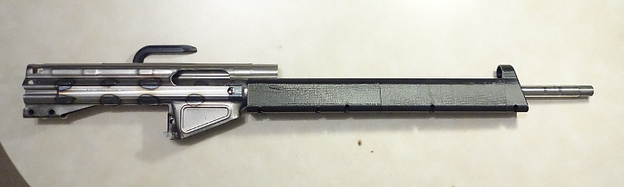
Since the whole point of all of this was to try to keep the bend straight and even, and keep the receiver shaped properly, how'd we do?  I'd say pretty good...

After taking the bolts out, I had to use a rubber mallet to get everything apart, and I had to hammer the mandrel out of the receiver.  I got a slight wave in the sheetmetal above the ejection port, but that's mostly due to my putting the cutout in the wrong place on the jig.  It's also much more noticeable here than it is in real life.  Look Ma, I made a gun! (from a legal standpoint anyway)


It turns out that the lower jig is also great for holding things while you're welding too.  I put my recovered G3 stock attachment weldment in the back of the receiver, used a piece of copper tubing as a backer for the front portion, clamped on a whole lot of Vice Grips, and welded it all up.  


Even though it should be Tigged to be correct, I Mig welded everything because that's what I have at the moment.  I've spent a whole lot of time doing sheetmetal work on cars, so welding up a receiver this thick was no problem.  The welds weren't factory Tig pretty, so I ground them all down and this is what I ended up with:

The true test of a CETME/HK folded flat is the bolt drop test.  Basically, you drop the bolt carrier through the receiver and it should freely drop through with no interference or drag.  I checked it after every step along the way.  So how'd I do?   Fresh off the jig: Perfect.  Tack welded: Perfect.  Fully welded: Perfect.  As best as I can tell, this receiver is as close to perfectly shaped as a home build can get.

And what of our jig, how did it hold up?  Pretty good. One of the add on end pieces I superglued on the mandrel came off, but it was a glue failure, not a print failure(the files I'll post will have that as one piece).  The lower just has a few scrapes in it, and a mushed spot where the ejection port flares out and that's about it, no other damage(and I'll fix the ejection port cutout in the file before I post it).  This thing worked so well that it could probably be done in a bench vice or with C-clamps, if you have some big enough, or possibly even by using 1/4" All Thread and some nuts to pull the two parts together with C-clamps for the middle.  Total cost for this jig was around $20 in filament, and about 3 days of print time.


If you want to make one for yourself, you can find my STLs here:

 https://www.thingiverse.com/thing:4614385


Getting jiggy with it

 Just a preview of my 3D printed CETME/G3 bending jig, mostly because I want to use the pic elsewhere on the internet.  Here's my printed jig all mocked up.  Hopefully I get some time to actually try this thing out this weekend.  The mandrel portion is made from more pieces than it needs to be because I changed my mind on the design half way through printing and didn't want to reprint the whole thing so I just added to what I already had.  The mandrel has a little gap in the middle too because I had to kill a print towards the end so I could leave for work and it ended up a little short(I don't like leaving the printer going when I'm not home).  I don't think the gap will affect how it works, but if it seems like it's going to cause a problem I can just print a little filler piece.  There are a few more pieces to it that aren't pictured, but we'll have to wait and see if it works like the picture in my head says it should.


Monday, September 14, 2020

I admit to cheating.

I've mentioned a few times that I've had to draw all the parts for my PSG-None from scratch.  So, how do I do that and get reasonably accurate parts without having any actual PSG-1 parts to measure?  Simple, I cheat.  Solidworks has a feature that allows you to import a picture as a sketch, the Sketch Picture command.  What I do is find the most direct side shot of the object that I want to copy, import it into Solidworks, then scale it to the appropriate size.  For this project, I used the two rear takedown pin holes as my scaling guide, because I can directly measure the distance between those holes on the parts I have.  I just made a sketch with some points the correct distance apart, and scaled the image so it matched.

Then it's just a matter of creating 3D objects using the 2D picture as a guide.  Something to watch out for is if the object in the picture is tipped or has some lens distortion.  In this case, the gun in the picture was photographed at a slightly upward angle instead of a direct side shot, so the stock especially has some noticeable distortion because it's tall and straight.  You have to account for that in your sketching, and fudge as necessary.  Here's what my new parts look like overlaid on the picture I used as a guide.


I tried to be as accurate as I could, but still had to use some artistic license because I don't have real parts to measure.  I spent hours scouring the internet for reference photos and did the best I could without having parts in hand, and they look nice but these are in no way interchangeable with real PSG-1 parts(nor are they really intended to be, if you want a real clone buy real parts).  I also had to make some changes to work with my CETME parts kit, most notably in the handguard so that it would fit with the CETME trunion and cocking tube.  I took a lot of liberties on that one...  Here are what the parts look like without the guide picture in the way.  Just have to print them out and then wait until I get the receiver together to see how they fit.


Something old and something new

It's been cold and rainy and I didn't want to go outside so I got some more work done on the PSG-None.  When I stared this project, I though it would be pretty straight forward because I'd already 3D printed a cosplay prop version of the PSG-1.  Yeah...not so much.  The file that I based my prop on was not even close to accurate, none of it was the right shape and it wasn't even close to something that would fit on a real receiver.  Good enough for what it was as a prop, but not good enough for me to want to use on this project.  So I ended up redrawing everything from scratch.  

I started with the pistol grip since it could be printed quickly for test fitting. While I was at it, I experimented with Cura's "Fuzzy Skin" option.  It's an option in Cure that makes the outer wall of the print jitter randomly, making it look fuzzy compared to the smooth lines of a standard print.  You can see in the picture where the fuzzy skin stops and standard skin starts.  At some point I'll post a how-to for getting the fuzzy skin only in areas where you want it.  Here are my first test pieces, the grip and palm shelf, on my CETME grip housing.  This is basically a rough draft, the final version will fit a little better, and will be a bit shorter.  The bottom of the grip on this print extends too far down.  Also, for what it's worth, I usually use grey for all my prototyping because it's easy to see where things are rubbing and material has to be removed to get things to fit right(just a handy tip for printing things you know you're going to have to file and fit).

After modifying the grip to my satisfaction, I moved onto the stock.  Here too, I drew everything from scratch.  I'm going to be using a G3 recoil assembly and buffer instead of the CETME parts.  I bought a whole recoil/stock unit because it was actually cheaper than just buying the recoil assembly alone, so I have a nice surplus green G3 stock to pull some measurements from too.  After drafting, I printed out the front chunk of stock to make sure it fit in the recoil assembly like it was supposed to.  It needed just a little tweaking to fit right, and after seeing the print I changed the shape of the front few inches to better match the real thing too, so the final part will look better than this first print.


Monday, September 7, 2020

Two birds, one stone...maybe...

Like many of the guns I've built so far,  CETMEs use a receiver flat that gets folded into a receiver shell.  I'm going to make my own bending jig because I can.  A problem with these flats is getting them folded straight and to the right size.  Instead of making a bending jig and a separate straightening mandrel, I'm going to try to do it all at once.  I'm going to use a 3D printed jig mostly to see how it works.  Instead of just a round rod in the center, I drew up a mandrel to match the contours of the inside of the receiver.  Hopefully it will keep things straight and symmetrical.  Since I have a large piece of G3 receiver left over, I decided to flatten it out and test my jig idea with it.  I printed out a 3" piece of jig for the test.  Here's how it looks before bending:

And after bending.  The jig pieces aren't even printed solid, it's only 8 walls and 25% infill, and it bent this chunk of receiver without breaking a sweat.  Just out of curiosity I kept pressing until I crushed the upper mandrel, and it took a lot more force to crush the jig than it did to bend the receiver chunk.  I have to do a little bit of tweaking on the mandrel shape, but so far it really shows promise.
When I tried my "crush to destruction" test, the lower jig didn't even flex.  There's a lot of contact surface area where the receiver is pushing down on it and the base is wider than the top to help keep the sides from flexing out.  The upper mandrel stayed pretty intact too, it crushed directly under where the pressure  from the press was applied.  Keep in mind that this wasn't printed solid either, just 8 walls and 25% infill too.  Here's the upper mandrel post-destructive test.  It didn't even really crack and there is no layer separation, it just kind of smooshed until the plastic tore. 


Seperation anxiety

Like many military guns of the post-war era, CETME rifles consist of a few hard parts in a sheetmetal receiver shell.  Since I need to reuse the parts, I need to liberate them from the receiver pieces included in the kit, and that's part of why I've put this project off as long as I have.  The most common method is to grind the spot welds thin then peel the sheetmetal off.  I started with the front trunion because it's the biggest/easiest piece.  I didn't even need to grind through the welds.  It looks like some of them were already broke and had been for a while, and the ones that weren't were pretty weak.  This should have been the most solidly mounted part of the whole receiver.  When you hear people say to be wary of the quality of Spanish guns, this is why...

The rest of the parts were, in fact, properly welded.  When buying the parts I needed I also bought a G3 rear receiver section to harvest the rear sight base and stock attachment weldment(though I won't be using the iron sights at all on this build it was cheaper this way).  Here are all the parts I scavenged along with what's left of the receiver pieces: